
Mazda seems to be using the COVID-19 lockdown to get fans stuck at home excited about what the brand has to offer in the near future. Earlier this week, we heard strong rumours that the new 6 would be a rear-wheel drive, straight-6, 3-Series competitor. And today, their latest Japanese patent application shows a very exciting in-wheel motor hybrid system that also mentions rotary engines! This is all a lot, so let’s break it down into two parts.
In-Wheel Motor hybrid system
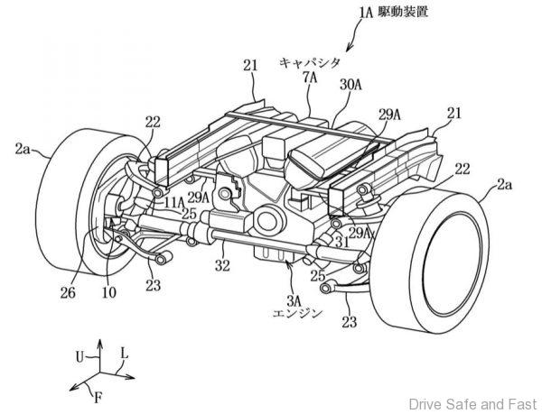
The patent revolves around a new all-wheel drive hybrid system with a combustion engine at the front, an electric motor at the rear, and another set of smaller electric motors in each of the front wheels. The system also integrates a rather small 3.5kWh lithium-ion battery and a capacitor. Energy recuperated from braking goes into the capacitor before charging the battery and the electric motors get their power from the capacitor first before trying the battery when the capacitor is “empty”.
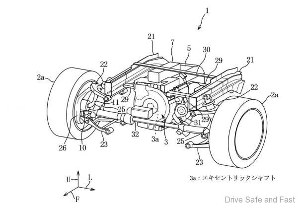
Low speed movement is done using a combination of the combustion engine and rear-mounted electric motor. At higher speeds, the in-wheel motors in the front are engaged.

Rotary Engines
Mazda are rumoured to be working on a rotary engine as a range extended for electric vehicles for a while. In this patent, rotary engines were mentioned, along with common inline and V engines as being compatible. In fact, the smaller package of a rotary engine would best suite this system. So, it’s still not concrete evidence that a rotary engine is confirmed, but it’s definitely something that’s being researched still.
PATENT TEXT
Japanese Patent Application No. 2018-187152 (P2018-187152)
(22) [Filing date] Heisei 30(2018) October 2 (2018.10.2)
(71) [Applicant]
[Identification Number]000003137
[Name]Mazda Motor Corporation
(57) [Overview]
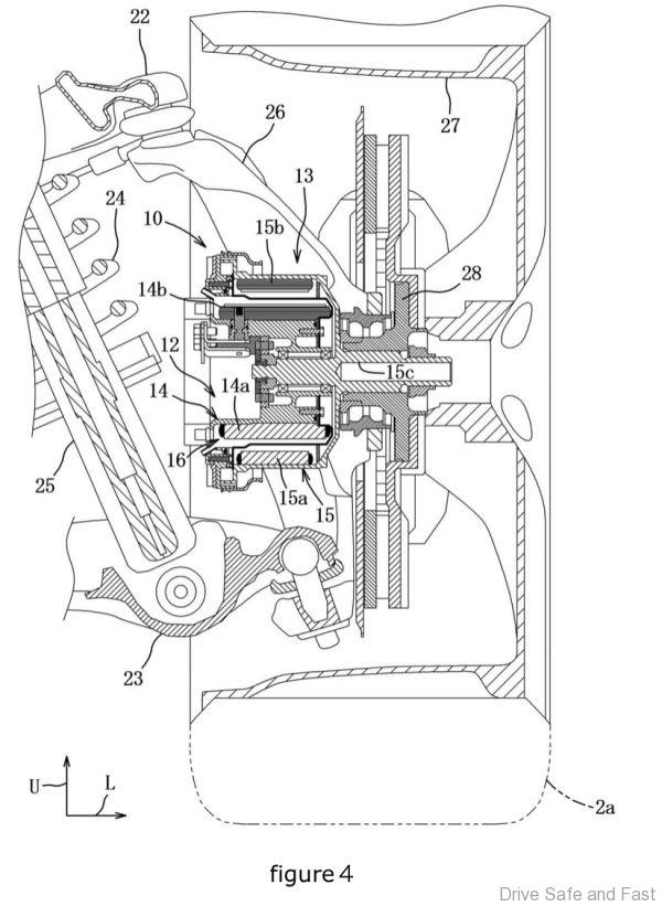
[Problem] To provide a driving device of a vehicle capable of securing both of an output of an in-wheel motor and a weight of a vehicle body by reducing a separation distance connecting an in-wheel motor and a capacitor.
[Means for solving] The driving device 1 includes an engine 3, a pair of left and right auxiliary driving motors 10 and composed of an in-wheel motor for driving the front wheels 2 a, and a battery 6 and a capacitor 7 capable of supplying driving power to the 1 pairs of sub driving motors 10 and. 1A battery 6 and a capacitor 7 are electrically connected in series, and a capacitor 7 is connected to the 1 pairs of sub drive motors 10 and and is arranged at an upper position of an engine 3 arranged between wheels of a front wheel 2 a.
[Selected drawing] Fig.2
[Patent Claims]
[Claim 1]
In the driving device of the vehicles which equipped an engine, the in-wheel motor of one pair of right and left which drive the wheel of one of right and left [ one pair of ] among two pairs of wheels approximately, respectively, and these one pairs of in-wheel motors with the battery and capacitor which can supply the electric power for a drive,
The battery and the capacitor are electrically connected in series.
A driving device for a vehicle, wherein the capacitor is connected to the 1 pair of in-wheel motors and is disposed at an upper position of the engine arranged between the 1 pairs of wheels in the vertical direction of the vehicle body.
[Claim 2]
The drive device of claim 1, wherein the engine is configured to drive the 1 pairs of wheels of the 2 pairs of wheels.
[Claim 3]
A drive device according to claim 1 or 2, wherein the engine is a rotary piston engine.
[Claim 4]
The engine is a V-type engine.
A vehicle drive device according to claim 1 or 2, wherein the capacitor is arranged between the V-banks.
[Claim 5]
The engine is obliquely arranged such that a crankshaft extends in the longitudinal direction of the vehicle body and an upper portion of the engine inclines toward either side of the vehicle width direction with respect to the lower portion.
The driving device for a vehicle according to claim 1 or 2, wherein the capacitor is disposed at an upper position in the vehicle body vertical direction than a vertical wall portion provided on the other side of the cylinder block of the engine in the vehicle width direction.
[Claim 6]
The engine is obliquely arranged such that a crankshaft extends in a vehicle width direction, and an upper portion of the engine inclines toward a vehicle body front-rear direction with respect to a lower portion.
A driving device for a vehicle according to claim 1 or 2, wherein the capacitor is disposed at an upper position in the vehicle body vertical direction than a vertical wall portion provided on the other side of the cylinder block of the engine in the vehicle body front-rear direction.
[Claim 7]
A vehicle drive system according to claim 1 or 2, wherein the engine is a horizontally opposed engine.
[Claim 8]
A vehicle drive device according to any one of claims 1 to 7, wherein a maximum voltage of the capacitor is set higher than a maximum voltage of the battery.